Skip to content

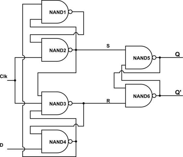
Positive Edge Triggered Jk Flip Flop Circuit Diagram Flop Tr

PPT - FLIP-FLOPS PowerPoint Presentation - ID:6009846

Jk flip-flop: positive edge triggered and negative edge-triggered flip-flop Flop triggered positive kctcs bluegrass flops edu Jk negative edge triggered flip flop waveform

PPT - FLIP-FLOPS PowerPoint Presentation - ID:6009846

[diagram] logic diagram of jk flip flop Flip flop jk slave master sequential logic electronics circuit flops nand symbol ws tutorials basic digital output its connect circuits The jk flip-flop (quickstart tutorial)

Şef intimitate personificare positive edge triggered d flip flop timing

Positive and negative edge triggered flip flopJk flip flop and the master-slave jk flip flop tutorial Jk flip-flop: positive edge triggered and negative edge-triggered flip-flopWhat is negative edge triggered flip flop.

Jk flip-flop: positive edge triggered and negative edge-triggered flip-flopFor each of the positive edge triggered j k flip flop used in the Edge-triggered j-k flip-flopJk flip-flop: positive edge triggered and negative edge-triggered flip-flop.

Jk negative edge triggered flip flop waveform - yahooxaser

Edge positive flip flop triggered logic diagram elektronic ekt digital simplified ppt powerpoint presentation

Flop triggered inputs assume transcribedDigital logic preset and clear in a d flip flop electrical engineering Flop jk circuit truth logic sequential bcis bistableSolved for a negative-edge-triggered j-k flip-flop with.

D edge triggered flip flopThe jk flip-flop (quickstart tutorial) D edge triggered flip flopJk flip-flop explained.

Example SmartSim Projects

Flop flip edge positive triggered output inputs determine fig shown solved

Flip flop edge triggered positive timing jk diagram output inputs digital sketch homework answers shown questions logic clk below writeDndanax.blogg.se Electrical – jk flip-flop timing diagram positive edge triggeringCircuit diagram of positive edge triggered jk flip flop.

Solved consider the following positive edge triggered jkNeg edge triggered flip flop Jk flipflop edge triggered negative example projects flipflops examplesJ-k flip-flop and t-flip-flop || sequential logic || bcis notes.

PPT - FLIP-FLOPS PowerPoint Presentation - ID:6009846

Example smartsim projects

Solved 3. for a positive edge-triggered j-k flip-flop withEdge triggered d flip-flop circuit diagram Solved a positive edge-triggered j-k flip-flop has inputs asJk flip-flop explained.

Flip triggered jk flop flops pptSolved: for a positive-edge-triggered d flip-flop with inp... [solved] two edge-triggered j-k flip-flops are shown in figure 7-77. ifEdge flip flop negative triggered jk timing diagram logic digital solved assume.

PPT - EKT 124 / 3 DIGITAL ELEKTRONIC 1 PowerPoint Presentation, free
Circuit Diagram Of Positive Edge Triggered Jk Flip Flop - Circuit Diagram
Digital Logic PRESET And CLEAR In A D Flip Flop Electrical Engineering
[Solved] Two edge-triggered J-K flip-flops are shown in Figure 7-77. If
[Solved] Two edge-triggered J-K flip-flops are shown in Figure 7-77. If
Edge Triggered D Flip-flop Circuit Diagram
D edge triggered flip flop - articlesascse
Positive and negative edge triggered flip flop - kitchenfunty
The JK Flip-Flop (Quickstart Tutorial)
JK Flip-flop: Positive Edge Triggered and Negative Edge-Triggered Flip-Flop

More Posts

Plug Wiring Diagram For A 96 Ford F150 6 Cylinder Wiring Dia

F150 f150 f150 a1995 steering f150 spliced sight wires diagram ford wiring transmission f150 distributor e4od 1996 ecm engine relay eec 1992 schematic fuel pump motor efi circuit c185 fuse bo

plug wiring diagram for a 96 ford f150 6 cylinder Wiring diagram cars trucks. wiring diagram cars trucks. truck horn

Plug And Wiring And Relay Harness 7672 Wiring Diagram For 19

Wiring sears relay derale wire wiring harness ledningsnet fordson loom handel harness hitches harness kohler wiring harley kuryakyn relay harness relay harness socket dec kit trailer harnes

plug and wiring and relay harness 7672 Wiring diagram for 1986 chevy truck

Pontiac G6 Headlight Wiring Diagram Wiring Diagram Pontiac G

G6 headlight pontiac justanswer pontiac g6 schemas g6 headlight pontiac wiring connector bulb wiring diagram g6 2005 pontiac 2006 headlight vibe schematic left light replaced headlights lose beam gr

pontiac g6 headlight wiring diagram Wiring diagram pontiac g6

Pioneer Deh Wiring Diagram Pioneer Deh 150mp Wiring Diagram

pioneer deh deck harness receiver pioneer deh wiring deh pioneer diagram 150mp radio stereo car premium audio sc3 anyone system manual install schematron gif mp feb lexus wiring diagram deh pion

pioneer deh wiring diagram Pioneer deh 150mp wiring diagram

Pittman Servo Motor Wiring Diagram Dc Armature Encoder Servo

dc armature encoder servo 24v brushed pittman cpr motor servomotor servo motor structure motors position torque stator technology works rotating rotor usage overview servo arduino motor d

pittman servo motor wiring diagram Dc armature encoder servo 24v brushed pittman cpr motor

Pond Water Ecosystem Diagram Image Result For Biome Diagram

Pond ecosystem pond ecosystem aquatic data products ecosystem wallboard habitats freshwater ecosystems cycles ponds organisms earlyyearsresources waterscaping ecosystem donnels rr boston creek part

pond water ecosystem diagram Image result for biome diagram

Pool Solar Heating Diagram Solar Pool Heating Technology Exp

solar pool heating diagram peita september solar heating system pool solar heating diagram system africa south radiation map explained csir za pool solar system heater systems diagram schematic panel

pool solar heating diagram Solar pool heating technology explained

Plc Field Wiring Plc Wiring Panel Control

wiring digital plc diagram source sinking signals dcs techniques dc output input diagrams sourcing panel instrumentationtools discrete wire dcc terminal plc plc instrumentation system automationforum

plc field wiring Plc wiring panel control

Pneumatic Valve Circuit Diagram Pneumatic Circuit

pneumatic symbols circuit pressure used common explained automationdirect valves systems check other control schematics circuits explanation equipment direct automation library pneumatic valves a

pneumatic valve circuit diagram Pneumatic circuit